You will find the chapter examples in the assets folder.
Translations started for Italian, German and Portuguese. Use the floating menu on the bottom right.
The source of this fork of the book is hosted on GitHub (fork temporarily used for translation). The original source is hosted on GitHub. The original source is hosted on Patches, suggestions and comments are welcome.

Effekte mit OpenGL (engl.)
Autor des Abschnitts: jryannel
Bemerkung
Last Build: März 14, 2018 at 02:55 CET
The source code for this chapter can be found in the assets folder.
Objective
- http://doc.qt.io/qt-5/qml-qtquick-shadereffect.html
- http://www.opengl.org/registry/doc/GLSLangSpec.4.20.6.clean.pdf
- http://www.khronos.org/registry/gles/specs/2.0/GLSL_ES_Specification_1.0.17.pdf
- http://www.lighthouse3d.com/opengl/glsl/
- http://wiki.delphigl.com/index.php/Tutorial_glsl
- Qt5Doc qtquick-shaders
Give a short introduction to shader effects and then present the shader effects and their use.
Shaders allows us to create awesome rendering effects on top to the SceneGraph API leveraging directly the power of OpenGL running on the GPU. Shaders are implemented using the ShaderEffect and ShaderEffectSource elements. The shader algorithm itself is implemented using the OpenGL Shading Language.
Practically it means you mix QML code with shader code. On execution will the shader code be sent over to the GPU and compiled and executed on the GPU. The shader QML elements allow you to interact through properties with the OpenGL shader implementation.
Let’s first have a look what OpenGL shaders are.
OpenGL Shaders
OpenGL uses a rendering pipeline split into stages. A simplified OpenGL pipeline would contain a vertex and fragment shader.
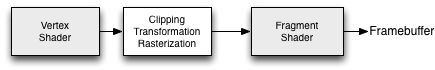
The vertex shader receives vertex data and must assign it to the gl_Position at the end of the routine. In the next stage the vertexes are clipped, transformed and rasterized for pixel output. From there the fragments (pixels) arrive in the fragment shader and can further be manipulated and the resulting color needs to be assigned to gl_FragColor. The vertex shader is called for each corner point of your polygon (vertex = point in 3D) and is responsible of any 3D manipulation of these points. The fragment (fragment = pixel) shader is called for each pixel and determines the color of that pixel.
Shader Elements
For programing shaders Qt Quick provides two elements. The ShaderEffectSource and the ShaderEffect. The shader effect applies custom shaders and the shader effect source renders a QML item into a texture and renders it. As shader effect can apply a custom shaders to it’s rectangular shape and can use sources for the shader operation. A source can be an image, which is used as a texture or a shader effect source.
The default shader uses the source and renders it unmodified.
import QtQuick 2.5

Rectangle {
    width: 480; height: 240
    color: '#1e1e1e'

    Row {
        anchors.centerIn: parent
        spacing: 20
        Image {
            id: sourceImage
            width: 80; height: width
            source: 'assets/tulips.jpg'
        }
        ShaderEffect {
            id: effect
            width: 80; height: width
            property variant source: sourceImage
        }
        ShaderEffect {
            id: effect2
            width: 80; height: width
            // the source where the effect shall be applied to
            property variant source: sourceImage
            // default vertex shader code
            vertexShader: "
                uniform highp mat4 qt_Matrix;
                attribute highp vec4 qt_Vertex;
                attribute highp vec2 qt_MultiTexCoord0;
                varying highp vec2 qt_TexCoord0;
                void main() {
                    qt_TexCoord0 = qt_MultiTexCoord0;
                    gl_Position = qt_Matrix * qt_Vertex;
                }"
            // default fragment shader code
            fragmentShader: "
                varying highp vec2 qt_TexCoord0;
                uniform sampler2D source;
                uniform lowp float qt_Opacity;
                void main() {
                    gl_FragColor = texture2D(source, qt_TexCoord0) * qt_Opacity;
                }"
        }
    }
}
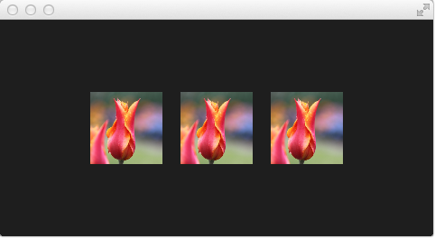
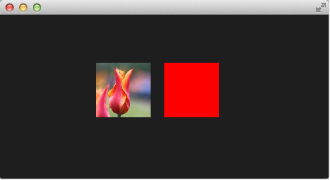
In the above example we have a row of 3 images. The first is the real image. The second is rendered using the default shader and the third is rendered using the default shader code for the fragment and vertex extracted from the Qt 5 source code.
Bemerkung
If you don’t want to see the source image and only the effected image you can set the Image to invisible (visible : false). The shader effects will still use the image data just the Image element will not be rendered.
Let’s have a closer look at the shader code.
vertexShader: "
    uniform highp mat4 qt_Matrix;
    attribute highp vec4 qt_Vertex;
    attribute highp vec2 qt_MultiTexCoord0;
    varying highp vec2 qt_TexCoord0;
    void main() {
        qt_TexCoord0 = qt_MultiTexCoord0;
        gl_Position = qt_Matrix * qt_Vertex;
    }"
Both shaders are from the Qt side a string bound to the vertexShader and fragmentShader property. Every shader code has to have a main() { ... } function, which is executed by the GPU. Variable starting with qt_ are provided by default by Qt already.
Here a short rundown on the variables:
| uniform | value does not change during processing |
| attribute | linkage to external data |
| varying | shared value between shaders |
| highp | high precision value |
| lowp | low precision value |
| mat4 | 4x4 float matrix |
| vec2 | 2=dim float vector |
| sampler2D | 2D texture |
| float | floating scalar |
A better reference is the OpenGL ES 2.0 API Quick Reference Card
Now we might be better able to understand what the variable are:
- qt_Matrix: model-view-projection matrix
- qt_Vertex: current vertex position
- qt_MultiTexCoord0: texture coordinate
- qt_TexCoord0: shared texture coordinate
So we have available the projection matrix, the current vertex and the texture coordinate. The texture coordinate relates to the texture given as source. In the main() function we store the texture coordinate for later use in the fragment shader. Every vertex shader need to assign the gl_Position this is done using here by multiplying the project matrix with the vertex, our point in 3D.
The fragment shader receives our texture coordinate from the vertex shader and also the texture from our QML source property. It shall be noted how easy it is to pass variable between the shader code and QML. Beautiful. Additional we have the opacity of the shader effect available as qt_Opacity. Every fragment shader needs to assign the gl_FragColor variable, this is done in the default shader code by picking the pixel from the source texture and multiplying it with the opacity.
fragmentShader: "
    varying highp vec2 qt_TexCoord0;
    uniform sampler2D source;
    uniform lowp float qt_Opacity;
    void main() {
        gl_FragColor = texture2D(source, qt_TexCoord0) * qt_Opacity;
    }"
During the next examples we will playing around with some simple shader mechanics. First we concentrate on the fragment shader and then we will come back to the vertex shader.
Fragment Shaders
The fragment shader is called for every pixel to be rendered. We will develop a small red lens, which will increase the red color channel value of the image.
Setting up the scene
First we setup our scene, with a grid centered in the field and our source image be displayed.
import QtQuick 2.5

Rectangle {
    width: 480; height: 240
    color: '#1e1e1e'

    Grid {
        anchors.centerIn: parent
        spacing: 20
        rows: 2; columns: 4
        Image {
            id: sourceImage
            width: 80; height: width
            source: 'assets/tulips.jpg'
        }
    }
}
A red shader
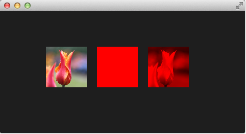
Next we will add a shader, which displays a red rectangle by providing for each fragment a red color value.
            fragmentShader: "
                uniform lowp float qt_Opacity;
                void main() {
                    gl_FragColor = vec4(1.0, 0.0, 0.0, 1.0) * qt_Opacity;
                }"
In the fragment shader we simply assign a vec4(1.0, 0.0, 0.0, 1.0) which represents a red color with full opacity (alpha=1.0) to the gl_FragColor for each fragment.
A red shader with texture
Now we want to apply the red color to each texture pixel. For this we need the texture back in the vertex shader. As we don’t do anything else in the vertex shader the default vertex shader is enough for us.
        ShaderEffect {
            id: effect2
            width: 80; height: width
            property variant source: sourceImage
            visible: root.step>1
            fragmentShader: "
                varying highp vec2 qt_TexCoord0;
                uniform sampler2D source;
                uniform lowp float qt_Opacity;
                void main() {
                    gl_FragColor = texture2D(source, qt_TexCoord0) * vec4(1.0, 0.0, 0.0, 1.0) * qt_Opacity;
                }"
        }
The full shader contains now back our image source as variant property and we have left out the vertex shader, which if not specified is the default vertex shader.
In the fragment shader we pick the texture fragment texture2D(source, qt_TexCoord0) and apply the red color to it.
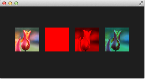
The red channel property
It’s not really nice to hard code the red channel value, so we would like to control the value from the QML side. For this we add a redChannel property to our shader effect and also declare a uniform lowp float redChannel inside our fragment shader. That’s all to make a value from the shader code available to the QML side. Very simple.
        ShaderEffect {
            id: effect3
            width: 80; height: width
            property variant source: sourceImage
            property real redChannel: 0.3
            visible: root.step>2
            fragmentShader: "
                varying highp vec2 qt_TexCoord0;
                uniform sampler2D source;
                uniform lowp float qt_Opacity;
                uniform lowp float redChannel;
                void main() {
                    gl_FragColor = texture2D(source, qt_TexCoord0) * vec4(redChannel, 1.0, 1.0, 1.0) * qt_Opacity;
                }"
        }
To make the lens really a lens, we change the vec4 color to be vec4(redChannel, 1.0, 1.0, 1.0) so that the other colors are multiplied by 1.0 and only the red portion is multiplied by our redChannel variable.
The red channel animated
As the redChannel property is just a normal property it can also be animated as all properties in QML. So we can use QML properties to animate values on the GPU to influence our shaders. How cool is that!
        ShaderEffect {
            id: effect4
            width: 80; height: width
            property variant source: sourceImage
            property real redChannel: 0.3
            visible: root.step>3
            NumberAnimation on redChannel {
                from: 0.0; to: 1.0; loops: Animation.Infinite; duration: 4000
            }

            fragmentShader: "
                varying highp vec2 qt_TexCoord0;
                uniform sampler2D source;
                uniform lowp float qt_Opacity;
                uniform lowp float redChannel;
                void main() {
                    gl_FragColor = texture2D(source, qt_TexCoord0) * vec4(redChannel, 1.0, 1.0, 1.0) * qt_Opacity;
                }"
        }
Here the final result.
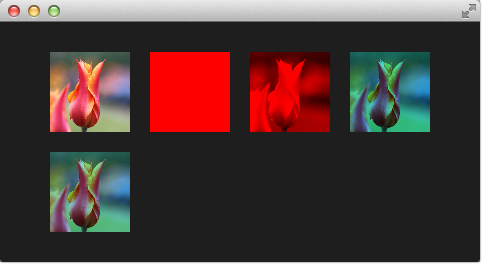
The shader effect on the 2nd row is animated from 0.0 to 1.0 with a duration of 4 seconds. So the image goes from no red information (0.0 red) over to a normal image (1.0 red).
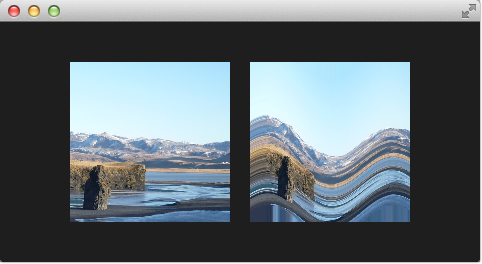
Wave Effect
In this more complex example we will create a wave effect with the fragment shader. The wave form is based on the sinus curve and it influences the texture coordinates used for the color.
import QtQuick 2.5

Rectangle {
    width: 480; height: 240
    color: '#1e1e1e'

    Row {
        anchors.centerIn: parent
        spacing: 20
        Image {
            id: sourceImage
            width: 160; height: width
            source: "assets/coastline.jpg"
        }
        ShaderEffect {
            width: 160; height: width
            property variant source: sourceImage
            property real frequency: 8
            property real amplitude: 0.1
            property real time: 0.0
            NumberAnimation on time {
                from: 0; to: Math.PI*2; duration: 1000; loops: Animation.Infinite
            }

            fragmentShader: "
                varying highp vec2 qt_TexCoord0;
                uniform sampler2D source;
                uniform lowp float qt_Opacity;
                uniform highp float frequency;
                uniform highp float amplitude;
                uniform highp float time;
                void main() {
                    highp vec2 pulse = sin(time - frequency * qt_TexCoord0);
                    highp vec2 coord = qt_TexCoord0 + amplitude * vec2(pulse.x, -pulse.x);
                    gl_FragColor = texture2D(source, coord) * qt_Opacity;
                }"
        }
    }
}
The wave calculation is based on a pulse and the texture coordinate manipulation. The pulse equation gives us a sine wave depending on the current time and the used texture coordinate:
highp vec2 pulse = sin(time - frequency * qt_TexCoord0);
Without the time factor we would just have a distortion but not a traveling distortion, like waves are.
For the color we use the color at a different texture coordinate:
highp vec2 coord = qt_TexCoord0 + amplitude * vec2(pulse.x, -pulse.x);
The texture coordinate is influences by our pulse x-value. The result of this is a moving wave.
Also if we haven’t moved pixels in this fragment shader the effect would look at first like a job for a vertex shader.
Vertex Shader
The vertex shader can be used to manipulated the vertexes provided by the shader effect. In normal cases the shader effect has 4 vertexes (top-left, top-right, bottom-left and bottom-right). Each vertex reported is from type vec4. To visualize the vertex shader we will program a genie effect. This effect is often used to let a rectangular window area vanish into one point.
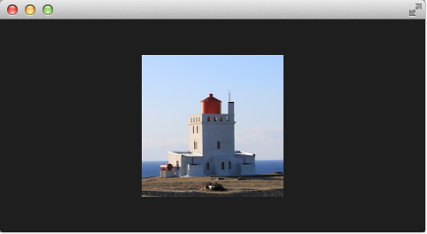
Setting up the scene
First we will setup our scene again.
import QtQuick 2.5

Rectangle {
    width: 480; height: 240
    color: '#1e1e1e'

    Image {
        id: sourceImage
        width: 160; height: width
        source: "assets/lighthouse.jpg"
        visible: false
    }
    Rectangle {
        width: 160; height: width
        anchors.centerIn: parent
        color: '#333333'
    }
    ShaderEffect {
        id: genieEffect
        width: 160; height: width
        anchors.centerIn: parent
        property variant source: sourceImage
        property bool minimized: false
        MouseArea {
            anchors.fill: parent
            onClicked: genieEffect.minimized = !genieEffect.minimized
        }
    }
}
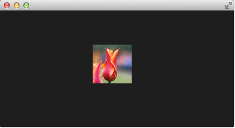
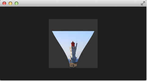
This provides as a scene with a dark background and a shader effect using an image as the source texture. The original image is not visible on the image produced by our genie effect. Additional we added a dark rectangle on the same geometry as the shader effect so we can better detect where we need to click to revert the effect.
The effect is triggered by clicking on the image, this is defined by the mouse area covering the effect. In the onClicked handler we toggle the custom boolean property minimized. We will use this property later to toggle the effect.
Minimize and normalize
After we have setup the scene, we define a property of type real called minimize, the property will contain the current value of our minimization. The value will vary from 0.0 to 1.0 and is controlled by a sequential animation.
        property real minimize: 0.0

        SequentialAnimation on minimize {
            id: animMinimize
            running: genieEffect.minimized
            PauseAnimation { duration: 300 }
            NumberAnimation { to: 1; duration: 700; easing.type: Easing.InOutSine }
            PauseAnimation { duration: 1000 }
        }

        SequentialAnimation on minimize {
            id: animNormalize
            running: !genieEffect.minimized
            NumberAnimation { to: 0; duration: 700; easing.type: Easing.InOutSine }
            PauseAnimation { duration: 1300 }
        }
The animation is triggered by the togling of the minimized property. Now that we have setup all our surroundings we finally can look at our vertex shader.
        vertexShader: "
            uniform highp mat4 qt_Matrix;
            attribute highp vec4 qt_Vertex;
            attribute highp vec2 qt_MultiTexCoord0;
            varying highp vec2 qt_TexCoord0;
            uniform highp float minimize;
            uniform highp float width;
            uniform highp float height;
            void main() {
                qt_TexCoord0 = qt_MultiTexCoord0;
                highp vec4 pos = qt_Vertex;
                pos.y = mix(qt_Vertex.y, height, minimize);
                pos.x = mix(qt_Vertex.x, width, minimize);
                gl_Position = qt_Matrix * pos;
            }"
The vertex shader is called for each vertex so four times, in our case. The default qt defined parameters are provided, like qt_Matrix, qt_Vertex, qt_MultiTexCoord0, qt_TexCoord0. We have discussed the variable already earlier. Additional we link the minimize, width and height variables from our shader effect into our vertex shader code. In the main function we store the current texture coordinate in our qt_TexCoord0 to make it available to the fragment shader. Now we copy the current position and modify the x and y position of the vertex:
highp vec4 pos = qt_Vertex;
pos.y = mix(qt_Vertex.y, height, minimize);
pos.x = mix(qt_Vertex.x, width, minimize);
The mix(...) function provides a linear interpolation between the first 2 parameters on the point (0.0-1.0) provided by the 3rd parameter. So in our case we interpolate for y between the current y position and the hight based on the current minimize value, similar for x. Bear in mind the minimize value is animated by our sequential animation and travels from 0.0 to 1.0 (or vice versa).
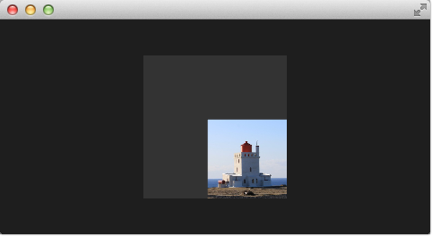
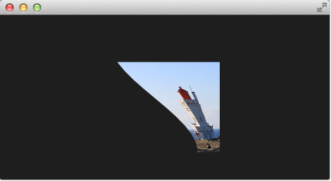
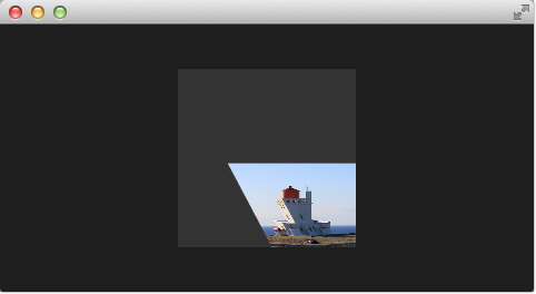
The resulting effect is not really the genie effect but is already a great step towards it.
Zu tun
better explanation, maybe draw the 4 vertexes and their interpolation
Primitive Bending
So minimized the x and y components of our vertexes. Now we would like to slightly modify the x manipulation and make it depending of the current y value. The needed changes are pretty small. The y-position is calculated as before. The interpolation of the x-position depends now on the vertexes y-position:
highp float t = pos.y / height;
pos.x = mix(qt_Vertex.x, width, t * minimize);
This results into an x-position tending towards the width when the y-position is larger. In other words the upper 2 vertexes are not affect ed at all as they have an y-position of 0 and the lower two vertexes x-positions both bend towards the width, so they bend towards the same x-position.
import QtQuick 2.5

Rectangle {
    width: 480; height: 240
    color: '#1e1e1e'

    Image {
        id: sourceImage
        width: 160; height: width
        source: "assets/lighthouse.jpg"
        visible: false
    }
    Rectangle {
        width: 160; height: width
        anchors.centerIn: parent
        color: '#333333'
    }
    ShaderEffect {
        id: genieEffect
        width: 160; height: width
        anchors.centerIn: parent
        property variant source: sourceImage
        property real minimize: 0.0
        property bool minimized: false


        SequentialAnimation on minimize {
            id: animMinimize
            running: genieEffect.minimized
            PauseAnimation { duration: 300 }
            NumberAnimation { to: 1; duration: 700; easing.type: Easing.InOutSine }
            PauseAnimation { duration: 1000 }
        }

        SequentialAnimation on minimize {
            id: animNormalize
            running: !genieEffect.minimized
            NumberAnimation { to: 0; duration: 700; easing.type: Easing.InOutSine }
            PauseAnimation { duration: 1300 }
        }


        vertexShader: "
            uniform highp mat4 qt_Matrix;
            uniform highp float minimize;
            uniform highp float height;
            uniform highp float width;
            attribute highp vec4 qt_Vertex;
            attribute highp vec2 qt_MultiTexCoord0;
            varying highp vec2 qt_TexCoord0;
            void main() {
                qt_TexCoord0 = qt_MultiTexCoord0;
                // M1>>
                highp vec4 pos = qt_Vertex;
                pos.y = mix(qt_Vertex.y, height, minimize);
                highp float t = pos.y / height;
                pos.x = mix(qt_Vertex.x, width, t * minimize);
                gl_Position = qt_Matrix * pos;
Better Bending
As the bending is not really satisfying currently we will add several parts to improve the situation. First we enhance our animation to support an own bending property. This is necessary as the bending should happen immediately and the y-minimization should be delayed shortly. Both animation have in the sum the same duration (300+700+1000 and 700+1300).
        property real bend: 0.0
        property bool minimized: false


        // change to parallel animation
        ParallelAnimation {
            id: animMinimize
            running: genieEffect.minimized
            SequentialAnimation {
                PauseAnimation { duration: 300 }
                NumberAnimation {
                    target: genieEffect; property: 'minimize';
                    to: 1; duration: 700;
                    easing.type: Easing.InOutSine
                }
                PauseAnimation { duration: 1000 }
            }
            // adding bend animation
            SequentialAnimation {
                NumberAnimation {
                    target: genieEffect; property: 'bend'
                    to: 1; duration: 700;
                    easing.type: Easing.InOutSine }
                PauseAnimation { duration: 1300 }
            }
        }
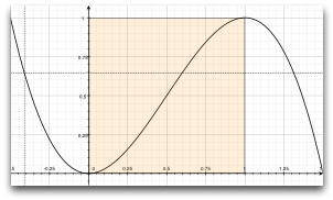
Additional to make the bending a smooth curve the y-effect on the x-position is not modified by a curved function from 0..1 and the pos.x depends now on the new bend property animation:
highp float t = pos.y / height;
t = (3.0 - 2.0 * t) * t * t;
pos.x = mix(qt_Vertex.x, width, t * bend);
The curve starts smooth at the 0.0 value, grows then and stops smoothly towards the 1.0 value. Here is a plot of the function in the specified range. For us only the range from 0..1 is from interest.
The most visual change is by increasing our amount of vertex points. The vertex points used can be increased by using a mesh:
mesh: GridMesh { resolution: Qt.size(16, 16) }
The shader effect now has an equality distributed grid of 16x16 vertexes instead of the 2x2 vertexes used before. This makes the interpolation between the vertexes look much smoother.
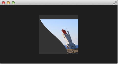
You can see also the influence of the curve being used, as the bending smoothes at the end nicely. This is where the bending has the strongest effect.
Choosing Sides
As a final enhancement we want to be able to switch sides. The side is towards which point the genie effect vanishes. Till now it vanishes always towards the width. By adding a side property we are able to modify the point between 0 and width.
ShaderEffect {
    ...
    property real side: 0.5

    vertexShader: "
        ...
        uniform highp float side;
        ...
        pos.x = mix(qt_Vertex.x, side * width, t * bend);
    "
}
Packaging
The last thing to-do is package our effect nicely. For this we extract our genie effect code into an own component called GenieEffect. It has the shader effect as the root element. We removed the mouse area as this should not be inside the component as the triggering of the effect can be toggled by the minimized property.
import QtQuick 2.5

ShaderEffect {
    id: genieEffect
    width: 160; height: width
    anchors.centerIn: parent
    property variant source
    mesh: GridMesh { resolution: Qt.size(10, 10) }
    property real minimize: 0.0
    property real bend: 0.0
    property bool minimized: false
    property real side: 1.0


    ParallelAnimation {
        id: animMinimize
        running: genieEffect.minimized
        SequentialAnimation {
            PauseAnimation { duration: 300 }
            NumberAnimation {
                target: genieEffect; property: 'minimize';
                to: 1; duration: 700;
                easing.type: Easing.InOutSine
            }
            PauseAnimation { duration: 1000 }
        }
        SequentialAnimation {
            NumberAnimation {
                target: genieEffect; property: 'bend'
                to: 1; duration: 700;
                easing.type: Easing.InOutSine }
            PauseAnimation { duration: 1300 }
        }
    }

    ParallelAnimation {
        id: animNormalize
        running: !genieEffect.minimized
        SequentialAnimation {
            NumberAnimation {
                target: genieEffect; property: 'minimize';
                to: 0; duration: 700;
                easing.type: Easing.InOutSine
            }
            PauseAnimation { duration: 1300 }
        }
        SequentialAnimation {
            PauseAnimation { duration: 300 }
            NumberAnimation {
                target: genieEffect; property: 'bend'
                to: 0; duration: 700;
                easing.type: Easing.InOutSine }
            PauseAnimation { duration: 1000 }
        }
    }

    vertexShader: "
        uniform highp mat4 qt_Matrix;
        attribute highp vec4 qt_Vertex;
        attribute highp vec2 qt_MultiTexCoord0;
        uniform highp float height;
        uniform highp float width;
        uniform highp float minimize;
        uniform highp float bend;
        uniform highp float side;
        varying highp vec2 qt_TexCoord0;
        void main() {
            qt_TexCoord0 = qt_MultiTexCoord0;
            highp vec4 pos = qt_Vertex;
            pos.y = mix(qt_Vertex.y, height, minimize);
            highp float t = pos.y / height;
            t = (3.0 - 2.0 * t) * t * t;
            pos.x = mix(qt_Vertex.x, side * width, t * bend);
            gl_Position = qt_Matrix * pos;
        }"
}
You can use now the effect simply like this:
import QtQuick 2.5

Rectangle {
    width: 480; height: 240
    color: '#1e1e1e'

    GenieEffect {
        source: Image { source: 'assets/lighthouse.jpg' }
        MouseArea {
            anchors.fill: parent
            onClicked: parent.minimized = !parent.minimized
        }
    }
}
We have simplified the code by removing our background rectangle and we assigned the image directly to the effect, instead of loading it inside a standalone image element.
Curtain Effect
In the last example for custom shader effects I would like to bring you the curtain effect. This effect was published first in May 2011 as part of Qt labs for shader effects.
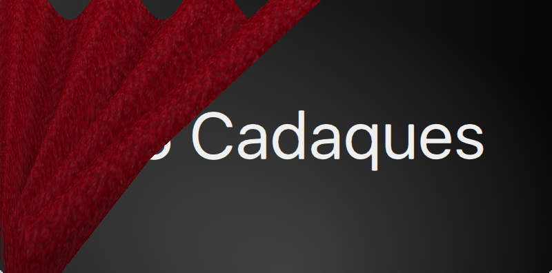
At that time I really loved these effects and the curtain effect was my favorite out of them. I just love how the curtain opens and hide the background object.
I took the code and adapted it towards Qt 5, which was straightforward. Also O did some simplifications to be able to use it better for a showcase. So if you are interested in the full example, please visit the labs blog.
Just a little bot for the background, the curtain is actually an image called fabric.jpg and it is the source for a shader effect. The effect uses the vertex shader to swing the curtain and uses the fragment shader to provide some shades. Here is a simple diagram to make you hopefully better understand the code.
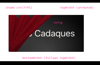
The waved shades of the curtain are computed through a sin curve with 7 up/downs (7*PI=21.99...) on the width of the curtain. The other important part is the swing. The topWidth of the curtain is animated when the curtain is opened or closed. The bottomWidth follows the topWidth with a SpringAnimation. By this we create the effect of the swinging bottom part of the curtain. The calculated swing provides the strength of this swing interpolated over the y-component of the vertexes.
The curtain effect is located in the CurtainEffect.qml component where the fabric image act as the texture source. There is nothing new on the use of shaders here, only a different way to manipulate the gl_Position in the vertex shader and the gl_FragColor in the fragment shader.
import QtQuick 2.5

ShaderEffect {
    anchors.fill: parent

    mesh: GridMesh {
        resolution: Qt.size(50, 50)
    }

    property real topWidth: open?width:20
    property real bottomWidth: topWidth
    property real amplitude: 0.1
    property bool open: false
    property variant source: effectSource

    Behavior on bottomWidth {
        SpringAnimation {
            easing.type: Easing.OutElastic;
            velocity: 250; mass: 1.5;
            spring: 0.5; damping: 0.05
        }
    }

    Behavior on topWidth {
        NumberAnimation { duration: 1000 }
    }


    ShaderEffectSource {
        id: effectSource
        sourceItem: effectImage;
        hideSource: true
    }

    Image {
        id: effectImage
        anchors.fill: parent
        source: "assets/fabric.png"
        fillMode: Image.Tile
    }

    vertexShader: "
        attribute highp vec4 qt_Vertex;
        attribute highp vec2 qt_MultiTexCoord0;
        uniform highp mat4 qt_Matrix;
        varying highp vec2 qt_TexCoord0;
        varying lowp float shade;

        uniform highp float topWidth;
        uniform highp float bottomWidth;
        uniform highp float width;
        uniform highp float height;
        uniform highp float amplitude;

        void main() {
            qt_TexCoord0 = qt_MultiTexCoord0;

            highp vec4 shift = vec4(0.0, 0.0, 0.0, 0.0);
            highp float swing = (topWidth - bottomWidth) * (qt_Vertex.y / height);
            shift.x = qt_Vertex.x * (width - topWidth + swing) / width;

            shade = sin(21.9911486 * qt_Vertex.x / width);
            shift.y = amplitude * (width - topWidth + swing) * shade;

            gl_Position = qt_Matrix * (qt_Vertex - shift);

            shade = 0.2 * (2.0 - shade ) * ((width - topWidth + swing) / width);
        }"

    fragmentShader: "
        uniform sampler2D source;
        varying highp vec2 qt_TexCoord0;
        varying lowp float shade;
        void main() {
            highp vec4 color = texture2D(source, qt_TexCoord0);
            color.rgb *= 1.0 - shade;
            gl_FragColor = color;
        }"
}
The effect is used in the curtaindemo.qml file.
import QtQuick 2.5

Item {
    id: root
    width: background.width; height: background.height


    Image {
        id: background
        anchors.centerIn: parent
        source: 'assets/background.png'
    }

    Text {
        anchors.centerIn: parent
        font.pixelSize: 48
        color: '#efefef'
        text: 'Qt5 Cadaques'
    }

    CurtainEffect {
        id: curtain
        anchors.fill: parent
    }

    MouseArea {
        anchors.fill: parent
        onClicked: curtain.open = !curtain.open
    }
}
The curtain is opened through a custom open property on the curtain effect. We use a MouseArea to trigger the opening and closing of the curtain.
Qt GraphicsEffect Library
The graphics effect library is a collection of shader effects. Ready made by the Qt developers. It’s a great tool-set to be used in your application but also a great source to learn how to build shaders.
The graphics effects library comes with a so called manual testbed which is a great tool to interactively discover the different effects.
The testbed is located under $QTDIR/qtgraphicaleffects/tests/manual/testbed.
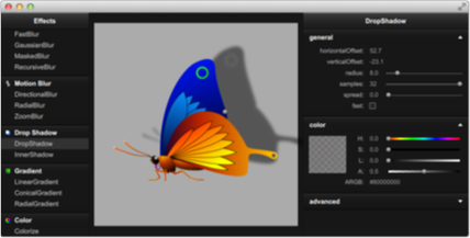
The effects library contains ca 20 effects. A list of the effect and a short description can be found below.
Graphics Effects List
| Category | Effect | Description |
|---|---|---|
| Blend | Blend | merges two source items by using a blend mode |
| Color | BrightnessContrast | adjusts brightness and contrast |
| Colorize | sets color in the HSL color space | |
| ColorOverlay | applies a color layer | |
| Desaturate | reduces color saturation | |
| GammaAdjust | adjusts luminance | |
| HueSaturation | adjusts colors in the HSL color space | |
| LevelAdjust | adjusts colors in the RGB color space | |
| Gradient | ConicalGradient | draws a conical gradient |
| LinearGradient | draws a linear gradient | |
| RadialGradient | draws a radial gradient | |
| Distortion | Displace | moves the pixels of the source item according to the specified displacement source |
| Drop Shadow | DropShadow | draws a drop shadow |
| InnerShadow | draws an inner shadow | |
| Blur | FastBlur | applies a fast blur effect |
| GaussianBlur | applies a higher quality blur effect | |
| MaskedBlur | applies a varying intensity blur effect | |
| RecursiveBlur | blurs repeatedly, providing a strong blur effect | |
| Motion Blur | DirectionalBlur | applies a directional motion blur effect |
| RadialBlur | applies a radial motion blur effect | |
| ZoomBlur | applies a zoom motion blur effect | |
| Glow | Glow | draws an outer glow effect |
| RectangularGlow | draws a rectangular outer glow effect | |
| Mask | OpacityMask | masks the source item with another item |
| ThresholdMask | masks the source item with another item and applies a threshold value |
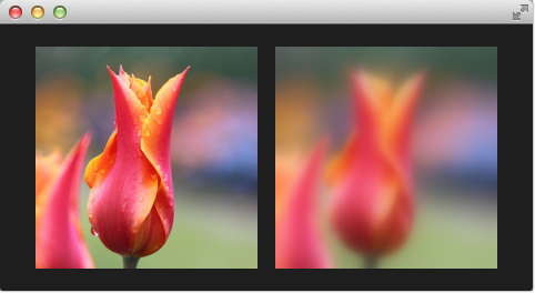
Here is a example using the FastBlur effect from the Blur category:
import QtQuick 2.5
import QtGraphicalEffects 1.0

Rectangle {
    width: 480; height: 240
    color: '#1e1e1e'

    Row {
        anchors.centerIn: parent
        spacing: 16

        Image {
            id: sourceImage
            source: "assets/tulips.jpg"
            width: 200; height: width
            sourceSize: Qt.size(parent.width, parent.height)
            smooth: true
        }

        FastBlur {
            width: 200; height: width
            source: sourceImage
            radius: blurred?32:0
            property bool blurred: false

            Behavior on radius {
                NumberAnimation { duration: 1000 }
            }

            MouseArea {
                id: area
                anchors.fill: parent
                onClicked: parent.blurred = !parent.blurred
            }
        }
    }
}
The image to the left is the original image. Clicking the image on the right will toggle blurred property and animated the blur radius from 0 to 32 during 1 second. The image on the left show the blurred image.